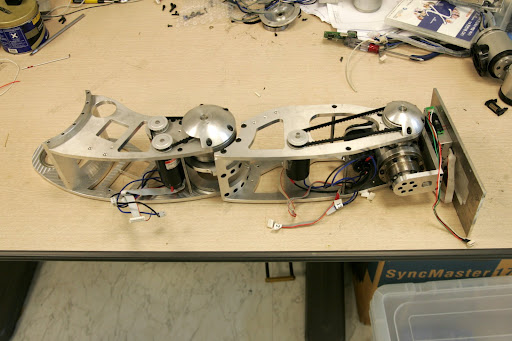
 The left leg of the Hubo is a sophisticated mix of art, engineering and subtle cleverness. The leg has a total of 6 DOF: 3 in the hip, one at the knee, and two at the ankle. These movements allow the Hubo to have almost human leg articulation. Missing from this picture are the stacks of motor driver boards which power the joints.
The design is a compromise between machining simplicity and compactness. In less critical areas like the leg structure, relatively simple machined plates support all of the parts. In areas such the hip joint (right) and ankle joint(below), the opposite is true.
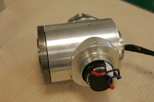
The hip joint design bypasses belts and pulleys seen on the knee and ankle, and places the servo inside the joint. It attaches directly to the harmonic drive (the end of the motor and encoder is visible in the picture).
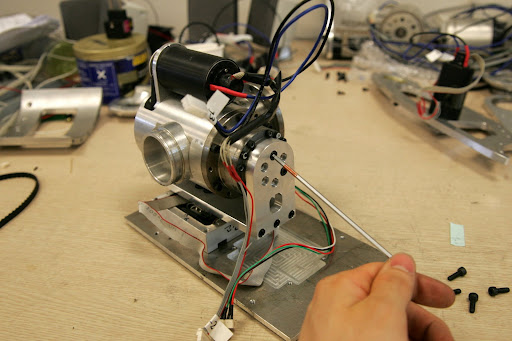
The ankle joint combines 2 axes as well, but without resorting to the internal drive arrangement in the hip. Instead, a shaft connects the drive belt/pulley from the motor to the drive on the other side of the joint. The lower belt and motor seen on the assembled leg drives the other joint, which turns on the bearing visible to the left.
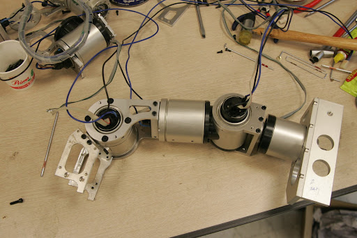 The arm (left) is a good example of design with inverse kinematics in mind. A human shoulder, for example, is a ball joint, with muscles attached to pull in various directions. While this allows 1 joint surface to do the work of 3, and simplifies the mechanism, it complicates the control problem immensely. With 3 axes working in parallel, there is no unique series of motions for the muscles to move the arm through a given path.
The Hubo arm uses a series arrangement of joint axes as shown. The first rotates the whole arm, the second swings the arm, and the last rotates the arm around this new axis. since all 3 axes intersect, it acts like a single joint. Since the angular velocity between successive bodies is simple, the inverse kinematics can be easily written.
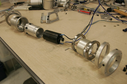 Each of the shoulder joints, as well as the elbow joint use a sophisticated internal-servo design to save space. Shown to the right is an exploded view of all the parts that make up one joint. the servo attaches to a small harmonic drive body, which then meshes with a gear inside the body of the joint. The 2 bearings allow the motor and inside of the harmonic drive to turn freely wrt the outside. This arrangement allows the outside to turn at a greatly reduced speed wrt the inside.
No comments:
Post a Comment