2007/07/27

The "brains" of hubo are this little PC: A mini-ITX board running an 800MHz Pentium-III. Power is drawn from the distribution board shown below, which can run from any DC source.
The hubo computer runs Windows XP; besides being a familiar environment, this feature makes it easy to connect to (USB, serial), move data, and debug with a keyboard and mouse.


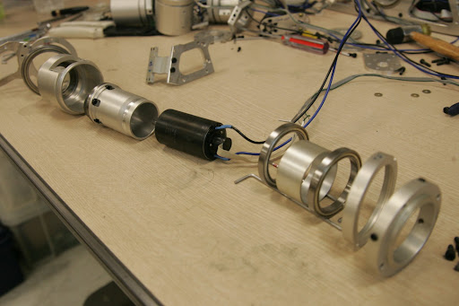
These parts make up the testing station. Motors, controllers, IMU's and force sensors interface just like they would on a normal hubo. The 2 small wires (yellow and black) connecting to the ITX board are the CAN interface, which connects the computer to all the peripherals in the system. This begs the question, what is a CAN and why is it used? A good technical summary can be found here (wikipedia). Practically, the advantages are clear: A CAN bus allows many different compatible devices to communicate over the same data lines. Each transmission packet has an overhead of about 6 bytes, and can transmit 0-8 bytes. The extensive header information gives each packet a unique encoding. Devices on the line can then be programmed only to receive or transmit data with a certain address. Wiring topology is thus determined by software, rather than hardware, making it easy to add/change sensors and drivers.

2007/07/11

An arm and a leg

The left leg of the Hubo is a sophisticated mix of art, engineering and subtle cleverness. The leg has a total of 6 DOF: 3 in the hip, one at the knee, and two at the ankle. These movements allow the Hubo to have almost human leg articulation. Missing from this picture are the stacks of motor driver boards which power the joints.

The design is a compromise between machining simplicity and compactness. In less critical areas like the leg structure, relatively simple machined plates support all of the parts. In areas such the hip joint (right) and ankle joint(below), the opposite is true.

The hip joint design bypasses belts and pulleys seen on the knee and ankle, and places the servo inside the joint. It attaches directly to the harmonic drive (the end of the motor and encoder is visible in the picture).

The ankle joint combines 2 axes as well, but without resorting to the internal drive arrangement in the hip. Instead, a shaft connects the drive belt/pulley from the motor to the drive on the other side of the joint. The lower belt and motor seen on the assembled leg drives the other joint, which turns on the bearing visible to the left.

The arm (left) is a good example of design with inverse kinematics in mind. A human shoulder, for example, is a ball joint, with muscles attached to pull in various directions. While this allows 1 joint surface to do the work of 3, and simplifies the mechanism, it complicates the control problem immensely. With 3 axes working in parallel, there is no unique series of motions for the muscles to move the arm through a given path.


The Hubo arm uses a series arrangement of joint axes as shown. The first rotates the whole arm, the second swings the arm, and the last rotates the arm around this new axis. since all 3 axes intersect, it acts like a single joint. Since the angular velocity between successive bodies is simple, the inverse kinematics can be easily written.

Each of the shoulder joints, as well as the elbow joint use a sophisticated internal-servo design to save space. Shown to the right is an exploded view of all the parts that make up one joint. the servo attaches to a small harmonic drive body, which then meshes with a gear inside the body of the joint. The 2 bearings allow the motor and inside of the harmonic drive to turn freely wrt the outside. This arrangement allows the outside to turn at a greatly reduced speed wrt the inside.

2007/07/09

Starting from scratch - Electronics

The first 2 weeks here have been all about learning the basics of HUBO's construction.
My first lesson was to build a universal F2808 DSP board that the lab uses for microcontroller applications. This small and relatively simple board has all the challenges of proper soldering. Aligning the 2808 chip took 3 or 4 tries, as the slightest misalignment could make very small solder shorts. While the SMD resistors are labeled with a tiny code, the capacitors are differentiable only by size and color. The same size and color chip can be 2 or 3 orders of magnitude difference; if the wrong one is soldered on, it's almost impossible to diagnose afterwards.

The A/D board I built next functioned properly, though this time I had to contend with power components. The large copper area connecting to the DC/DC converter dissipated heat, making it tough to get a clean contact.


Next up was soldering the motor controller board. Lacking PSPICE, I designed a simple Excel sheet to account for all the components off of the schematic. I wrote a few formulas to convert component values to part numbers, which could then be sorted. Soldering all of one component at a time ensured that I missed none, and that only one kind of identical-looking part would be on the table at a time. For the amplifier, a neat little trick to get the MOSFETs to line up properly was to bolt them all to the heatsink first.


Other accomplishments:
  • Obtained copy of HUBO dynamic walking PhD thesis by Dr. Jung-Yup Kim
  • wrote a brief MATLAB simulation of a lab project: the pneumatic pogo-stick
  • Photo tour of important buildings in KAIST
  • Took a photographic sequence showing major steps of leg and arm assembly
  • Rebuilt 2 broken harmonic drives; learned assembly/repair technique for similar drives located throughout the chassis.
  • Assembled a DSP board and IMU A/D board from scratch
  • Assembled a complete motor controller set (controller and amplifier)